After building an automatic barrier project with Arduino, I created a small weather station using an ESP32.
The goal was simple: measure room temperature and humidity with a DHT11 sensor, then display the values on an LCD1602. I later improved the setup by adding a button to control the screen backlight.
Components
- ESP32 NodeMCU-32S
- DHT11 sensor
- 16-pin LCD1602
- 10 kΩ potentiometer for contrast
- Push button
- 2N2222A NPN transistor
- Resistors
- Breadboards and Dupont wires
Both photos show the same LCD1602. The apparent color difference comes from the lighting, viewing angle, and camera rendering.
First version — DHT11 and LCD
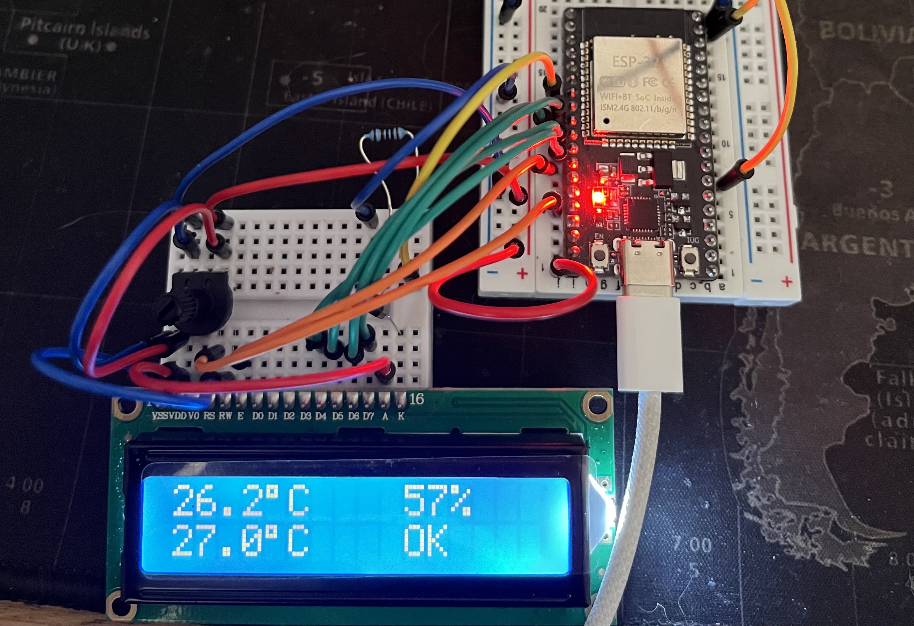
The first version measures:
- temperature;
- humidity;
- heat index.
The values are refreshed every three seconds.
The display alternates between:
- temperature and humidity;
- heat index and a COLD, OK, or HOT status.
The program also checks that the sensor readings are valid before displaying them.
Second version — Adding the button
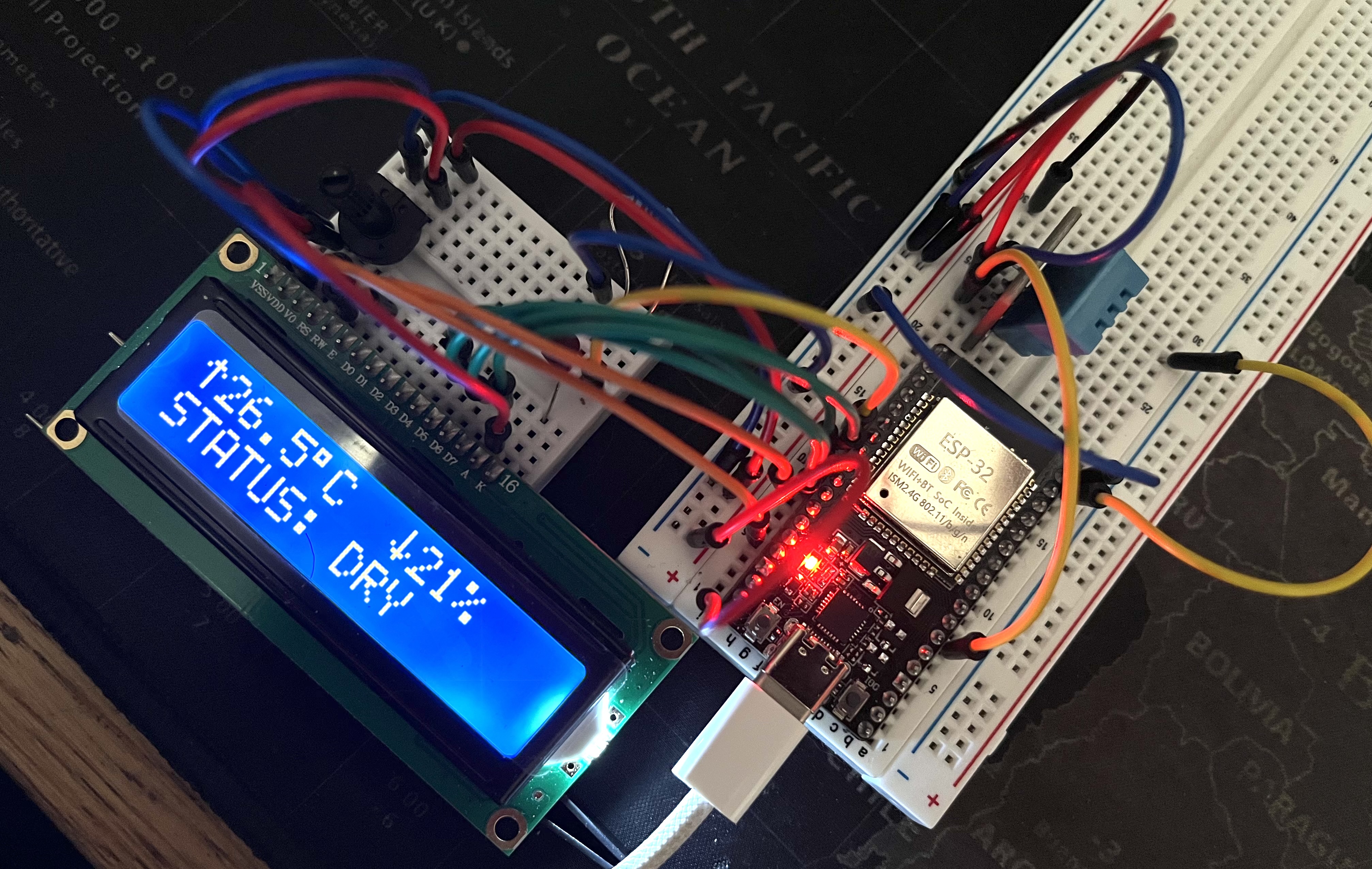
The second version keeps the same core behavior and adds:
- an ON/OFF button;
- backlight control;
- custom temperature and humidity icons;
- a humidity status: DRY, OPTIMAL, or WET.
The button does not shut down the weather station. It only turns off the backlight, while the ESP32 and sensor continue running.
Main wiring
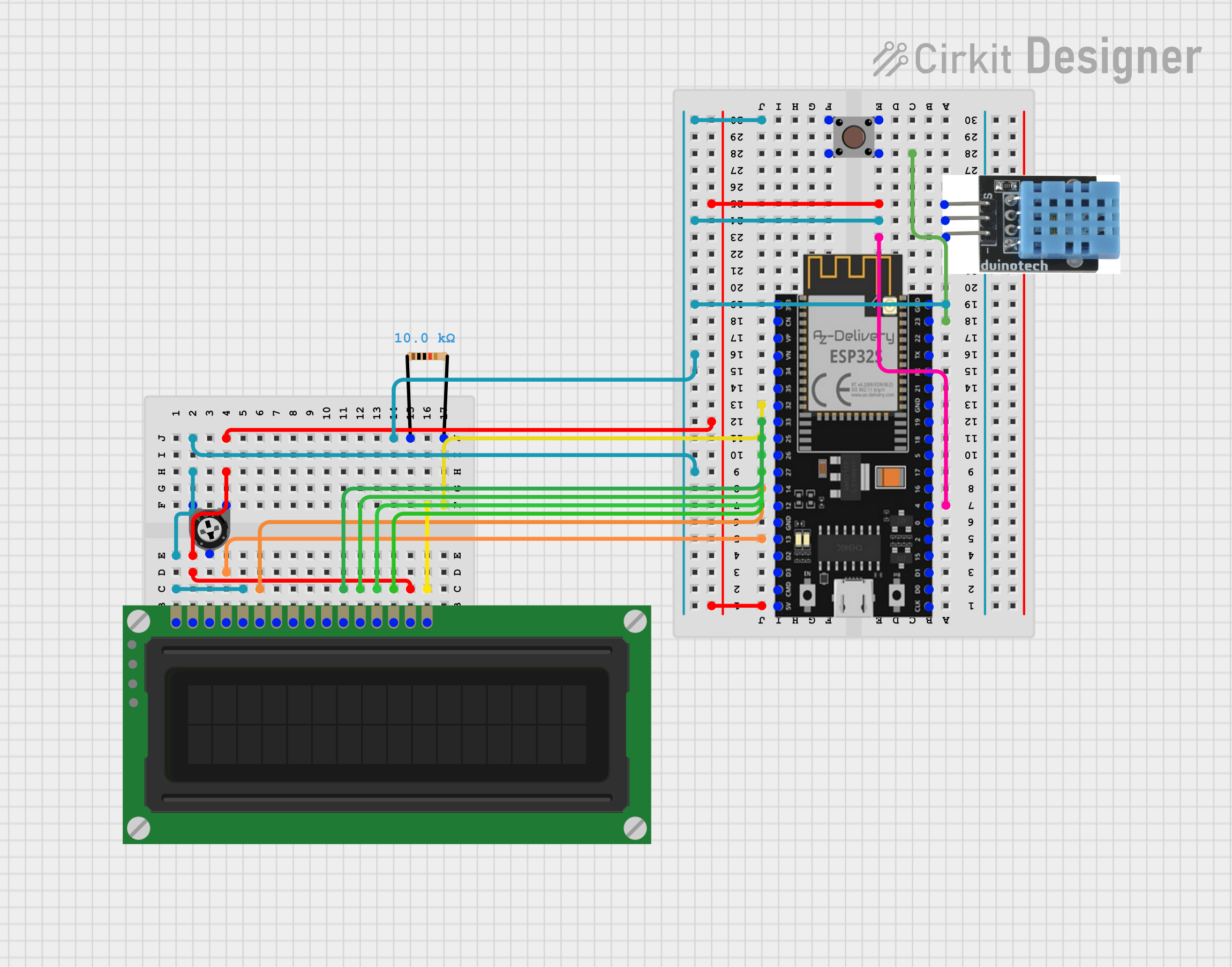
https://app.cirkitdesigner.com/project/293c2e20-7225-45bd-baa3-7935f3be398c
DHT11
- VCC → 3.3 V
- DATA → GPIO 4
- GND → GND
LCD1602
- VSS → GND
- VDD → 5 V
- V0 → potentiometer center pin
- RS → GPIO 13
- RW → GND
- E → GPIO 14
- D0 → not connected
- D1 → not connected
- D2 → not connected
- D3 → not connected
- D4 → GPIO 27
- D5 → GPIO 26
- D6 → GPIO 25
- D7 → GPIO 33
- A → 5 V through 220 Ω
- K → transistor collector
Pins D0 to D3 are not used. The 4-bit mode saves four GPIO pins without any visible drawback for this type of display.
10 kΩ potentiometer
- Outer pin → 5 V
- Center pin → LCD V0
- Outer pin → GND
The 10 kΩ potentiometer controls the screen contrast.
Push button
- Pin 1 → GPIO 23
- Opposite pin → GND
2N2222A transistor
- Base → GPIO 32 through 1 kΩ
- Collector → LCD K
- Emitter → GND
Button and backlight
- button connected between GPIO 23 and GND;
- GPIO 32 connected to the transistor base through a resistor;
- transistor used to control the backlight.
The transistor works as an electronic switch. The GPIO only sends a control signal and does not directly supply the backlight current.
Reading the sensor
float h = dht.readHumidity();
float t = dht.readTemperature();
if (isnan(h) || isnan(t)) {
  Serial.println("[DHT11] Read error");
  return;
}
isnan() means is Not a Number. This check prevents an invalid reading from being displayed as a real value.
Timing with millis()
if (currentTime - readingTimer >= 3000){
    readingTimer = currentTime;
    readSensors();
}
I use millis() instead of a delay(3000) inside the main loop.
This allows the ESP32 to keep monitoring the button while waiting for the next DHT11 reading.
Button handling
The button uses INPUT_PULLUP, which enables the ESP32's internal pull-up resistor.
The logic is therefore inverted:
- button released: HIGH;
- button pressed: LOW.
if (previousState == HIGH &&  currentState == LOW &&  currentTime - lastPress > 200) {
    backlightOn = !backlightOn;
}
The 200 ms delay acts as software debouncing. A mechanical button can generate several rapid electrical transitions during a single press.
Problems encountered
The screen was powered but blank
The issue was sometimes the contrast rather than the code. Adjusting the potentiometer made the characters visible.
One press was detected several times
Without debouncing, a single press could turn the backlight on and then off immediately.
Backlight control
The backlight requires more current than a GPIO should provide directly. I therefore used a transistor as a switch.
What I learned
This project helped me practice:
- reading a digital sensor;
- validating measurements with isnan();
- controlling an LCD1602 in 4-bit mode;
- creating custom LCD characters;
- non-blocking timing with millis();
- reading a button with INPUT_PULLUP;
- software debouncing;
- using a transistor as an electronic switch.
Result
The weather station continuously displays room temperature and humidity.
The first version validates the full sensor → processing → display chain. The second adds physical interaction and a clearer interface without changing the core operation.
The next planned improvements are replacing the DHT11 with a DHT22, adding a BMP280, and creating a Wi-Fi dashboard.